


Truth Tables & Logic Gates
Unit 7 Summary Part 4


Logic Gates' Symbols & Truth Tables (Outputs)


NOT gate
always converts 0 to 1, or 1 to 0.
AND gate
is restrictive, only outputs 1 if both inputs are 1.
OR gate
is flexible, always outputs 1 if at least there's 1 in one of the inputs.

Watch to know How to answer logic gates


Order of precedence
The drawings that should be done first in order:
-
Brackets
-
NOT
-
AND
-
OR

Oxford AQA IGCSE 2019
Analyze it yourself. It may seem difficult, but actually it's not.

02.1.
The logic circuit in Figure 1 can be represented by the Boolean expression:
Figure 1
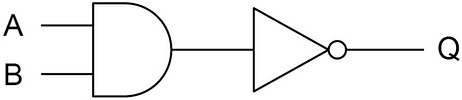
Complete the truth table for this logic circuit. [2 marks]

'·' means AND gate.
AND gate is restrictive, it only gives 1 if both inputs are 1.
Ā means NOT gate.
NOT gate converts 0 to 1 or 1 to 0.
So the answers are:


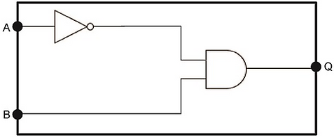
02.2.
Draw a circuit diagram for the Boolean expression: [3 marks]

Ā means NOT gate.
'·' means AND gate.
So the drawing is:

Oxford AQA IGCSE 2020
Analyze it yourself. It may seem difficult, but actually it's not.

07.1.
Complete the truth table below for the OR logic gate. [1 mark]

Answer:
OR gate is flexible, it always outputs 1 if at least there's 1 in one of the inputs.
So the answers are:

07.2.
A fire alarm makes a bell ring to warn people if there is a fire.
The alarm system has:
• A switch S which outputs 1 if the alarm system is turned on and 0 if it is turned off.
• A heat sensor H which outputs 1 if a fire has been automatically detected and 0 otherwise.
• A call point button C which a person can press if they see a fire. This outputs 1 if the button is pressed and 0 otherwise.
• An alarm bell B which rings when it receives a 1 as an input and does not ring when it receives a 0
The bell should ring when the system is turned on and either the heat sensor automatically detects a fire or the call point button is pressed.
Draw a logic circuit diagram in the space below for the fire alarm system. [3 marks]


Answer:
See the bolded sentence. That's your clue. Ignore the rest.
So the answer is:

Alternative answer:

07.3.
Write a Boolean expression that represents the alarm system described in question [2 marks]
B = ______________________________
Answer:
𝐒 ∙ (𝐇 + 𝐂)
Alternative answer:
𝐒 ∙ 𝐇 + 𝐒 ∙ 𝐂

Oxford AQA IGCSE Specimen Paper
Analyze it yourself. It may seem difficult, but actually it's not.

04.
Figure 2 shows a truth table for a logic gate.
Figure 2

04.1.
Shade in one box to indicate which logic gate the truth table in Figure 2 represents. [1 mark]
Figure 3 shows a logic circuit.
-
The circuit has two inputs, A and B.
-
The circuit has two outputs, X and Y.
Figure 3


04.2.
Complete the truth table below for the logic circuit in Figure 3. [5 marks]

04.3.
The logic circuit in Figure 3 performs a useful operation in binary. Look at the values of the circuit outputs X and Y for the different values of the inputs A and B. Explain the purpose of the circuit. [1 mark]
__________________________________________________________________________________

Oxford AQA IGCSE Mock Paper
Analyze it yourself. It may seem difficult, but actually it's not.

10.1.
Complete the Output column of the truth table below for an AND logic gate with inputs A and B and output Q. [1 mark]
__________________________________________________________________________________


10.2.
In the space below, draw a logic circuit for the Boolean expression: [4 marks]
__________________________________________________________________________________

